
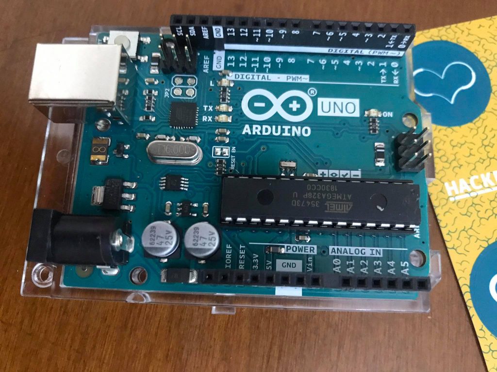
The Arduino Uno Rev3 is a microcontroller board based on the ATmega328 (datasheet). It has 14 digital input/output pins (of which 6 can be used as PWM outputs), 6 analog inputs, a 16 MHz crystal oscillator, a USB connection, a power jack, an ICSP header, and a reset button.
It contains everything needed to support the microcontroller; simply connect it to a computer with a USB cable or power it with a AC-to-DC adapter or battery to get started.
The Uno differs from all preceding boards in that it does not use the FTDI USB-to-serial driver chip. Instead, it features the Atmega8U2 programmed as a USB-to-serial converter.”Uno” means one in Italian and is named to mark the upcoming release of Arduino 1.0.
The Uno and version 1.0 will be the reference versions of Arduno, moving forward. The Uno is the latest in a series of USB Arduino boards, and the reference model for the Arduino platform. Microcontroller ATmega328Operating Voltage 5VInput Voltage (recommended) 7-12VInput Voltage (limits) 6-20VDigital I/O Pins 14 (of which 6 provide PWM output)Analog Input Pins 6DC Current per I/O Pin 40 mADC Current for 3.3V Pin 50 mAFlash Memory 32 KB of which 0.5 KB used by bootloaderSRAM 2 KBEEPROM 1 KBClock Speed 16 MHz
New features of the Arduino Uno Rev. 3
In addition to continuing all the advantages of the Duemilanove, the Arduino Uno Rev. 3 has a number of new features, particularly in terms of its USB interfacing hardware. You also have an Arduino pinout extension for your I2C pins and an IOREF pin for adapting your shield to the board regardless of its voltage (3.3 or 5V).
A second, unconnected pin is also available next to the IOREF pin in anticipation of subsequent uses.
Also note that the A000066 Arduino Uno Rev. 3 board is backward-compatible with the hardware used on Duemilanove and earlier versions of the Arduino Uno.
Finally, this board’s designers have replaced the ATmega8U2 with a more powerful ATmega16U2 chip.
Technical specifications of the A000066 Arduino Uno Rev. 3
- Microcontroller: ATmega328
- Operating voltage: 5V
- Recommended supply voltage: 7–12V
- Supply voltage (limits): 6–20V
- Digital I/O pins: 14 (including 6 providing PWM output)
- Analogue input pins: 6
- Direct current per I/O pin: 40 mA
- Direct current (3.3V pin): 50 mA
- Flash memory: 32 kB
- SRAM: 2 kB
- EEPROM: 1 kB
- Frequency: 16 MHz
Resources for the Arduino UNO R3 A000066
The open-source IDE can be downloaded for free (currently for Mac OS X, Windows, and Linux). Some tutorials are available on the official Arduino web site. These tutorials help you to write your first program with Arduino boards.

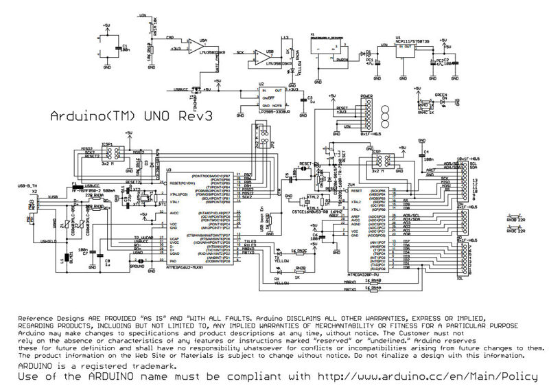
Eagle Files – Reference Design for Arduino Uno Rev3
Datasheet ATmega238P for Arduino Uno Rev3
Pin Description
| Pin Category | Pin Name | Details |
| Power | Vin, 3.3V, 5V, GND | Vin: Input voltage to Arduino when using an external power source.5V: Regulated power supply used to power microcontroller and other components on the board.3.3V: 3.3V supply generated by on-board voltage regulator. Maximum current draw is 50mA.GND: ground pins. |
| Reset | Reset | Resets the microcontroller. |
| Analog Pins | A0 – A5 | Used to provide analog input in the range of 0-5V |
| Input/Output Pins | Digital Pins 0 – 13 | Can be used as input or output pins. |
| Serial | 0(Rx), 1(Tx) | Used to receive and transmit TTL serial data. |
| External Interrupts | 2, 3 | To trigger an interrupt. |
| PWM | 3, 5, 6, 9, 11 | Provides 8-bit PWM output. |
| SPI | 10 (SS), 11 (MOSI), 12 (MISO) and 13 (SCK) | Used for SPI communication. |
| Inbuilt LED | 13 | To turn on the inbuilt LED. |
| TWI | A4 (SDA), A5 (SCA) | Used for TWI communication. |
| AREF | AREF | To provide reference voltage for input voltage. |
Arduino Uno Technical Specifications
| Microcontroller | ATmega328P – 8 bit AVR family microcontroller |
| Operating Voltage | 5V |
| Recommended Input Voltage | 7-12V |
| Input Voltage Limits | 6-20V |
| Analog Input Pins | 6 (A0 – A5) |
| Digital I/O Pins | 14 (Out of which 6 provide PWM output) |
| DC Current on I/O Pins | 40 mA |
| DC Current on 3.3V Pin | 50 mA |
| Flash Memory | 32 KB (0.5 KB is used for Bootloader) |
| SRAM | 2 KB |
| EEPROM | 1 KB |
| Frequency (Clock Speed) | 16 MHz |
Other Arduino Boards
Arduino Nano, Arduino Pro Mini, Arduino Mega, Arduino Due, Arduino Leonardo
Overview
Arduino Uno is a microcontroller board based on 8-bit ATmega328P microcontroller. Along with ATmega328P, it consists other components such as crystal oscillator, serial communication, voltage regulator, etc. to support the microcontroller. Arduino Uno has 14 digital input/output pins (out of which 6 can be used as PWM outputs), 6 analog input pins, a USB connection, A Power barrel jack, an ICSP header and a reset button.
How to use Arduino Board
The 14 digital input/output pins can be used as input or output pins by using pinMode(), digitalRead() and digitalWrite() functions in arduino programming. Each pin operate at 5V and can provide or receive a maximum of 40mA current, and has an internal pull-up resistor of 20-50 KOhms which are disconnected by default. Out of these 14 pins, some pins have specific functions as listed below:
- Serial Pins 0 (Rx) and 1 (Tx): Rx and Tx pins are used to receive and transmit TTL serial data. They are connected with the corresponding ATmega328P USB to TTL serial chip.
- External Interrupt Pins 2 and 3: These pins can be configured to trigger an interrupt on a low value, a rising or falling edge, or a change in value.
- PWM Pins 3, 5, 6, 9 and 11: These pins provide an 8-bit PWM output by using analogWrite() function.
- SPI Pins 10 (SS), 11 (MOSI), 12 (MISO) and 13 (SCK): These pins are used for SPI communication.
- In-built LED Pin 13: This pin is connected with an built-in LED, when pin 13 is HIGH – LED is on and when pin 13 is LOW, its off.
Along with 14 Digital pins, there are 6 analog input pins, each of which provide 10 bits of resolution, i.e. 1024 different values. They measure from 0 to 5 volts but this limit can be increased by using AREF pin with analog Reference() function.
- Analog pin 4 (SDA) and pin 5 (SCA) also used for TWI communication using Wire library.
Arduino Uno has a couple of other pins as explained below:
- AREF: Used to provide reference voltage for analog inputs with analogReference() function.
- Reset Pin: Making this pin LOW, resets the microcontroller.
Communication
Arduino can be used to communicate with a computer, another Arduino board or other microcontrollers. The ATmega328P microcontroller provides UART TTL (5V) serial communication which can be done using digital pin 0 (Rx) and digital pin 1 (Tx). An ATmega16U2 on the board channels this serial communication over USB and appears as a virtual com port to software on the computer. The ATmega16U2 firmware uses the standard USB COM drivers, and no external driver is needed. However, on Windows, a .inf file is required. The Arduino software includes a serial monitor which allows simple textual data to be sent to and from the Arduino board. There are two RX and TX LEDs on the arduino board which will flash when data is being transmitted via the USB-to-serial chip and USB connection to the computer (not for serial communication on pins 0 and 1). A SoftwareSerial library allows for serial communication on any of the Uno’s digital pins. The ATmega328P also supports I2C (TWI) and SPI communication. The Arduino software includes a Wire library to simplify use of the I2C bus.
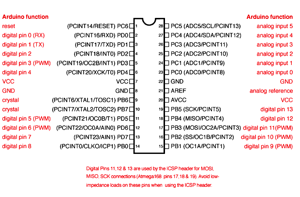
Arduino Uno to ATmega328 Pin Mapping
When ATmega328 chip is used in place of Arduino Uno, or vice versa, the image below shows the pin mapping between the two.
Software
Arduino IDE (Integrated Development Environment) is required to program the Arduino Uno board. Download it here.
Programming Arduino
Once arduino IDE is installed on the computer, connect the board with computer using USB cable. Now open the arduino IDE and choose the correct board by selecting Tools>Boards>Arduino/Genuino Uno, and choose the correct Port by selecting Tools>Port. Arduino Uno is programmed using Arduino programming language based on Wiring. To get it started with Arduino Uno board and blink the built-in LED, load the example code by selecting Files>Examples>Basics>Blink. Once the example code (also shown below) is loaded into your IDE, click on the ‘upload’ button given on the top bar. Once the upload is finished, you should see the Arduino’s built-in LED blinking. Below is the example code for blinking:
// the setup function runs once when you press reset or power the board
void setup() {
  // initialize digital pin LED_BUILTIN as an output.
  pinMode(LED_BUILTIN, OUTPUT);
}

// the loop function runs over and over again forever
void loop() {
  digitalWrite(LED_BUILTIN, HIGH);   // turn the LED on (HIGH is the voltage level)
  delay(1000);                       // wait for a second
  digitalWrite(LED_BUILTIN, LOW);    // turn the LED off by making the voltage LOW
  delay(1000);                       // wait for a second
}
Applications
- Prototyping of Electronics Products and Systems
- Multiple DIY Projects.
- Easy to use for beginner level DIYers and makers.
- Projects requiring Multiple I/O interfaces and communications.
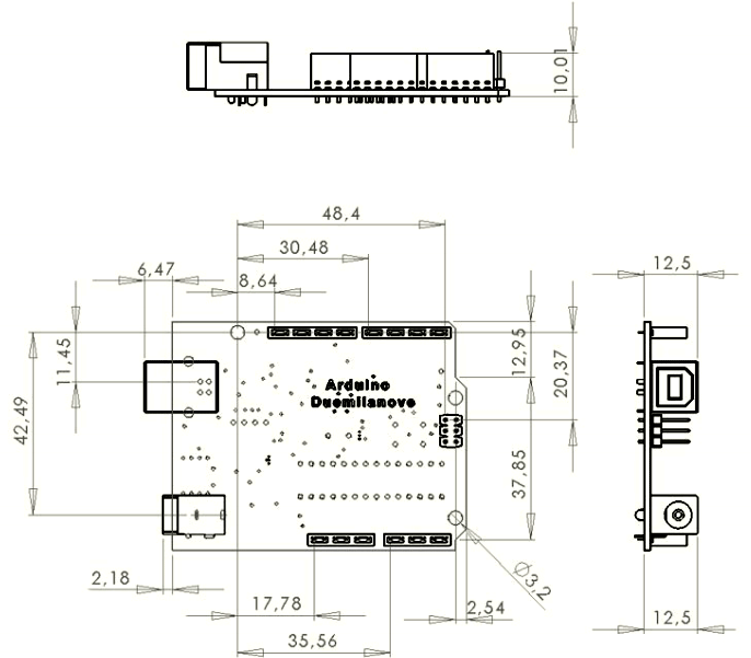
Arduino Uno 2D Model
Component DatasheetArduino Uno Datasheet